|
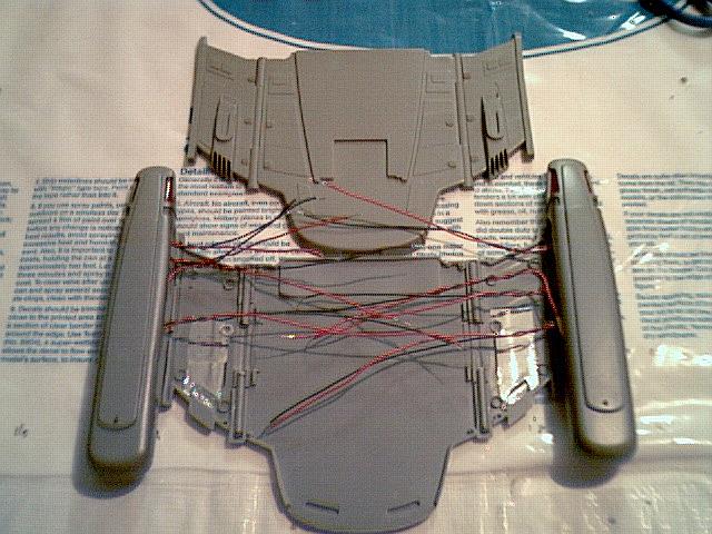
The warp nacelles and struts aren't going
to move on this model (it's going to be stuck in Impulse / Non-Warp)
because I have to find a way to get the wires from the nacelles and
struts through the hinges and into the body of the rear section.
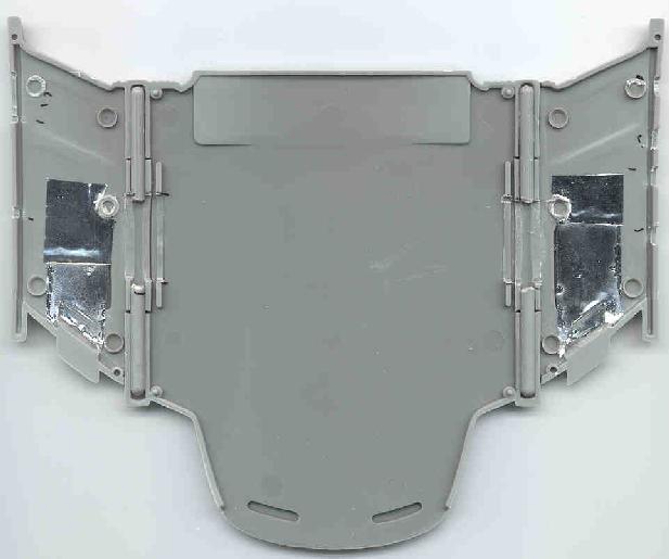
If you examine the image above, you'll see that I've cut notches where
the nacelles meet the struts so as to allow the wires through.
Also, I've removed sections from the hinges and glued them into place
on the bottom half to make room.
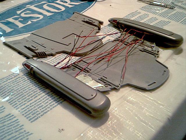
Also, the struts have their own structure to get around. It's
kind of difficult to describe, but where the struts attach to the
hinges the plastic forms a circle around them. I had to file
this down carefully, so that there was enough room to go through this
circle and the hinged components without filing through the plastic
that would show on the bottom and topside of the model. |