4/1/02

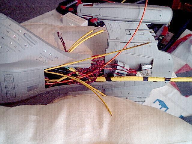
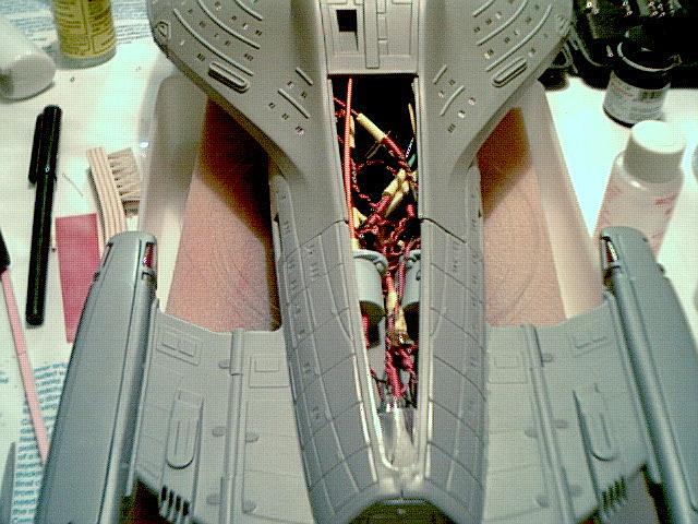
     I knew I was dealing with tight spaces, but I didn't appreciate just how tight.  Suddenly I was dealing with threading window fibre through wires, ensuring enough space was left for assembly and trying not to snap any if the window fibres.

     I lost and re-installed countless window fibres, the total loss count being about seven.

     I began by tightening up the space - putting coils in the wires so they would compress gracefully and bending them to allow space.  I then marked where I wanted the window fibres to go on the port side, and started drilling.

     Unfortunately the micro drill had long broken so I had to use the Dremel tool to hold the hair-thin drill bit, and remembering that I had difficulty on the starboard side with making the windows too large I experimented on the Enterprise-D and found that using the Dremel (turning at a minimum of 5,000 RPM) it melted the plastic practically on contact.  So, I had to drill the windows not just precisely, but fast.  Turns out I had just a couple of windows that weren't okay, but most of them I had to follow up with the drill bit and pliers because the hole sealed up with melted plastic after pulling out the bit! 

     It was very tedious.

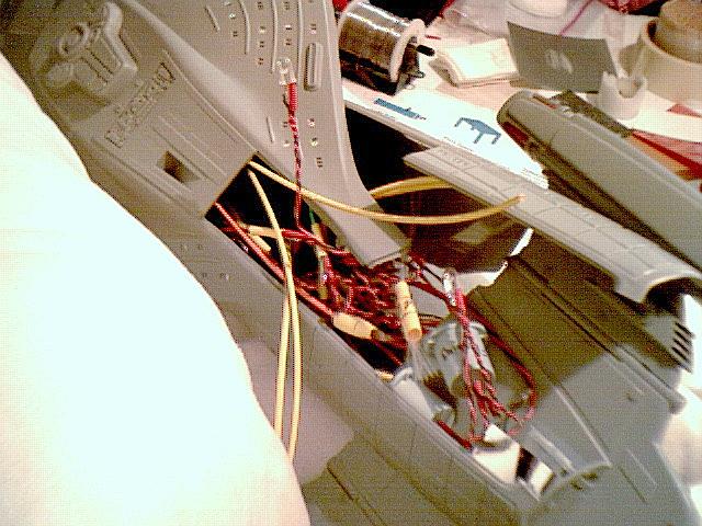
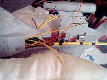
     After the holes were prepared, I then ran the window fibre into the holes backwards and threaded them through the wires and circuit board, guiding them to the aft of the ship for mounting to the fibre drivers.  
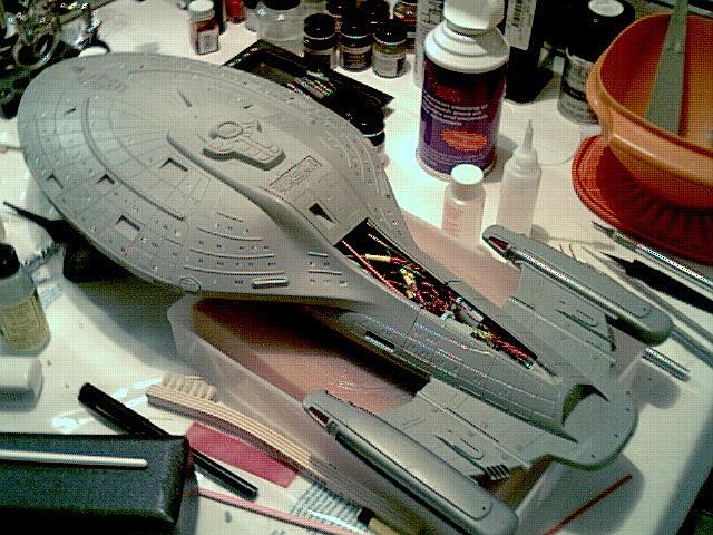
I then put the starboard section of the ship closer to the main hull for assembly.


     I've discovered a little trick - I purchased a keychain with a blue LED light on it that's extremely bright.  This little tool is fantastic for tracing fibre strands the diameter of a hair!  White light blends in with the room light, so while you can see the end of the fibre you still have to look for it.  If you use a blue light instead it stands out like a beacon - so brightly you can watch where you're holding the light and see which strand it is out of your peripheral vision.

     It makes tracking those strands a hell of a lot easier - if it weren't for this little thing I'd've lost my mind and my vision!


     Assembly then became a matter of keeping track of the strands and figuring out where to put them.  As I worked and tried to line them up with the right fibre drivers, I discovered that there was no way they were all going to fit like I wanted them to.  Not only that, but the fibre for the constant light on the bottom of the hull (3/18/02) kept coming unglued, such that it was impossible to mount the other end to the driver!  Trying to get all the strands into the collars I had created out of shrink tubing was damn near impossible, and it took many hours to get the strands together and in the right places.

     It was very painful.


     I finally succumbed to the fact that the two fibre drivers I had wouldn't be enough - the wide fibres from the saucer section refused to line up with the strands from the engineering section, and the fibre on the bottom of the hull refused to line up with the others on the port side without coming unglued.  As you can see from the picture above and to the right, what I ended up doing was splicing a white LED onto the fibre driver (port side, non-flashing) for a third driver, and using some shrink tubing to create a larger fibre driver, along the same lines as I used for the port and starboard indicators.

     Getting them all installed was painful.  Really.  It was horrible.  I finally managed to get them all together and into tight bundles, which were then polished and inserted into the fibre driver assemblies.

     Lighting the shuttle bay was joyously easy.  What I did prior to joining the drive section to the engineering section was use the Dremel tool to grind down the back so there would be room for light (less than 1cm, though).  At this point I put some shiny mylar over the tail and pointed a white LED from the base of the drive section up to that mylar so as to reflect the light into the shuttle bay.  It seems to work perfectly.


     Above are pictures of the completed innards, before placing the spine.   Everything is in its place.  In the tightest of sections there is no free space (threading fibres through with the wires), and in others there still isn't enough room to insert a pinkie.  The saucer section has the most room at about one, maybe two square inches in places.  The engineering section is flat out packed..

     But it's done.


     What follows is this:

  • paint the main deflector amplification grid blue, on the inside
  • paint the raised part of the deflector completely, then mount the deflector assembly
  • mask the deflector assembly
  • start pouring over the hull, using putty, filing and shaping and perfecting in preparation for paint