4/1/02

     It must first be said that I am in deep gratitude to Ed for the use of his soldering iron and Dremel tool - without their use I'd've been screwed.  The Dremel was used for evening, shaping, smoothing, buffing, cutting, drilling and contouring, and the soldering iron was simply perfect for the job. 

Thank you.

     This step of the Project was the hardest to date - there was nothing more intricate, delicate and downright hard than what was accomplished in the last 13 hours (construction of the nacelles was a close running).

     I've spent the last week playing touch-and-go, doing little things here and there.  Starting 4/1 at 1:00p I just tackled the whole thing with one goal - closure of the ship's hull.  I had no idea it was going to be so hard.

     Over the last week I accomplished a lot, but didn't update the site because I was winging every minute of it - things happened pretty fast.

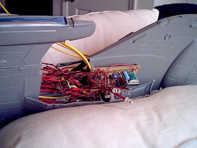
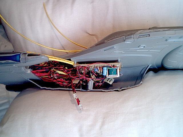
     The circuit board was mounted on the bottom of the saucer section such that the large fibres from the engineering section wrapped around the stand-offs, using them to make sure they wrapped around smoothly:


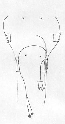
     Pardon the lousy drawing, but it at least gives you an idea of what I'm talking about.  The top is fore, bottom is aft, left is port and right is starboard.

     The large fibres that ran from the rear of the ship that need to flash were looped around the circuit board stand-offs to connect to the flashing fibre driver.  These larger diameter fibres snap if you bend them too quickly or sharply, so this curve needed to be gradual and slow.  The drawing at left shows how they loop around in the completed assembly - at this step the starboard side of the ship wasn't on yet, so they were just hanging in the breeze.


     Mounting the power jack was also extremely complicated.  I originally thought that I could just glue the top (joining end) to the bottom of the hull and call it good, but as I started fidgeting with it I realized that there was no way it could handle the stress of multiple connections and disconnections without some major reinforcement.

     I used some of the sprue to build a horse-shoe shaped reinforcement cage around the bottom and glued it to the bottom of the hull, then put more sprue along side the plug.  After experimenting to find out the best glue to use, I then ruthlessly glued it to the reinforcement cage, also using putty on the bottom to ensure the plug met the cage on all sides.

     The two blue LEDs on the front of the circuit board were bent so as to issue blue light all across the primary deflector array.

     Four white LEDs were put on wires straight off the circuit board so as to shine on the bay windows in the engineering section.  The white LEDs that light the port side bay windows were glued into place with some difficulty, as the large fibres that come from the engineering section actually touch the bay windows, so I had to glue the white LED between them using bulldogs and dental tools - very tricky.

    You can see the two on the starboard side in the pictures at right.  You can also see the yellow shrink tubing that is the engineering section flashing LED fibre, just hangin' out.


     I then installed the window fibre on the starboard section of the hull.  It was as this point that I started considering just where and how I was going to place these fibres, and I started realizing what I was in for.  I strived to place window fibre at random points just like I did on the saucer, knowing that I might lose a few but striving for the best.

     They were looped around and grouped into the shrink-tubing for neatness, though I didn't keep them in the tubing because when tubing bends, it snaps and it would snap the fibres with it.


     What follows is the nightmare that was putting all these pieces together.


Proceed to Part 2 - installation of fibre into fibre drivers and final assembly