


So here’s the scene – you’re having dinner in a restaurant on the patio, it’s a gorgeous night out and someone gets into their car in the lot and starts it, the headlights come on and there you are like a deer in headlights, except you’re a biped with thick soup and can now see the bottom of the bowl. Said person drives away, and now you can see nothing for five minutes.
It’s rude. Thing is, there’s little we can do about it nowadays because it’s impossible to turn off your lights – newer cars have this as a “safety feature” and I hate it; it’s my car, it should be able to do what I want it to. It took me a day and a half to re-wire my headlights to a switch, that’s a lot of work, a lot of hate and now it’s out of my system and my car will let me be polite. There are many reasons to black out a car – this is mine and I ran with it.
There were a great many learning experiences in this project that I thought I’d share. I couldn’t find the information I needed on any other site (and some were wrong), so I’m capturing my experiences here in the hopes it’ll save someone some time.
Project Goals
- One switch in the passenger compartment within easy reach will “black out” the car, turning off running lights and headlights. An indicator light on the switch shows the lights are enabled, if that indicator light is out then so are your lights.
- New cars have an onboard computer that controls just about everything – this work should be “easy” and not mess with the computer nor cause anomalies that it might consider a malfunction.
- This shouldn’t interfere with high/low beams or be affected by vehicle state, working consistently regardless of whether it’s running, off, parked, signaling to change lanes, etc.
- This needs to be safe – appropriately fused and insulated – so that it works just as well in a blizzard (because white snow amplifies light).
Recommendations
- It takes one amp to kill you and your car can generate orders of magnitude more than that – wear latex / nitrile gloves ALWAYS, be careful, play with cold circuits. Don’t plug in your work until you’re ready.
- Have an automotive volt meter on hand. Test circuits to make sure they’re cold, even when you think you’re sure.
- Test your connections for strength and continuity – wire crimp connectors can be flaky.
- Use shrink tubing to seal crimped connections or to make darn sure, after sleet, snow, vibrations and hot days, that they won’t come into contact with other things and cause a short. Electrical tape’s okay, but use shrink tubing where possible.
- Relays are your friend. There are many ways to directly wire circuits to the switch but they’ll almost always spark. Any spark is bad under any condition, but in a modern car this can cause micro-surges that could damage your electrical kit and main computer.
- Fuse every hot connection; my circuit has a line straight to the battery, and that line has a fuse on it first thing.
- Make sure your fuses are appropriate – not too high, not too low – for the current you’re dealing with. Too high a rating and it’ll just sit there while things melt, too low and it’ll burn out trying to do what it’s supposed to do.
- Use the fuse box as a guideline; if the headlights are normally fused at 10 amps, assume you’re dealing with a 10 amp circuit when it comes to buying wire for the project.
- Get a Chiltons (or other) manual for your car that has an electrical diagram and look it up. Even if you’re sure you already know, crosscheck. Circle and mark the circuits you’re dealing with.
- Work with the fuse box wherever possible. Messing directly with car wires is risky business.
- To test whether you have the right circuit, pull the fuse and see if you’re right. Blown fuses won’t destroy on board computers or wiring, that’s a “normal fault”. If you turn the car on but your headlights don’t come on, you’ve got the right fuse and circuit.
- Fuses have a polarity, each side isn’t the same – be aware if you’re tapping “hot” or ground.
How to switch a fuse
Messing with the fuse directly is the easiest way to go. If you could put a switch on top of a fuse then you can turn it on and off without cutting into original wiring. Thing is, they don’t make this kind of device (that I could find).
Enter the “Add-A-Circuit Fuse Tap, piggy back standard”.
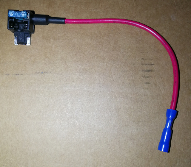
This little guy is intended to add a “hot” wire for you given project. You can put two fuses in each slot and have a normal fuse and a fused output. Good way to get clean power for other projects such as a radar detector, LIDAR jammer, etc.
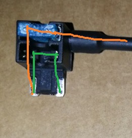
Zooming in on this thing, the picture at right show how it’s wired: green is the normal path, put a fuse in there and put it back in the fuse box and you have a normal circuit plus the “hot” (positive, with power) line coming out.
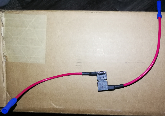
Turns out, if you take these things and piggy back them in the right direction you end up with a circuit path you can insert a switch into:
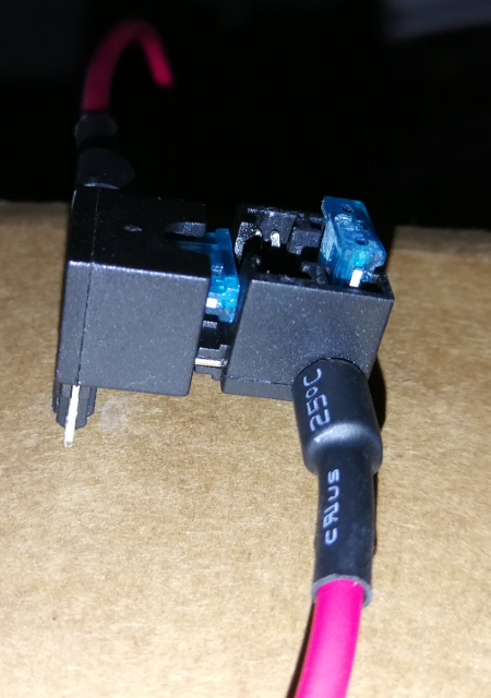
A close up view is at right, showing how you connect them. Fuses only go in the top slot and plug one into the bottom slot of the other, as shown.
Put a drop of super glue on top of one of the fuses and press it all together, it’ll keep things more sturdy. If a fuse blows, they twist apart just fine. Protip : If you put a higher rated fuse on the inside (harder to reach) and put the glue on top of that, then put a smaller rated fuse on the outside (easy to reach), the smaller, easy to reach one will always blow first!
NOTE : Not all fuse boxes have enough space for this unit to fit! This really screwed me, as you’ll see below.
How not to do it
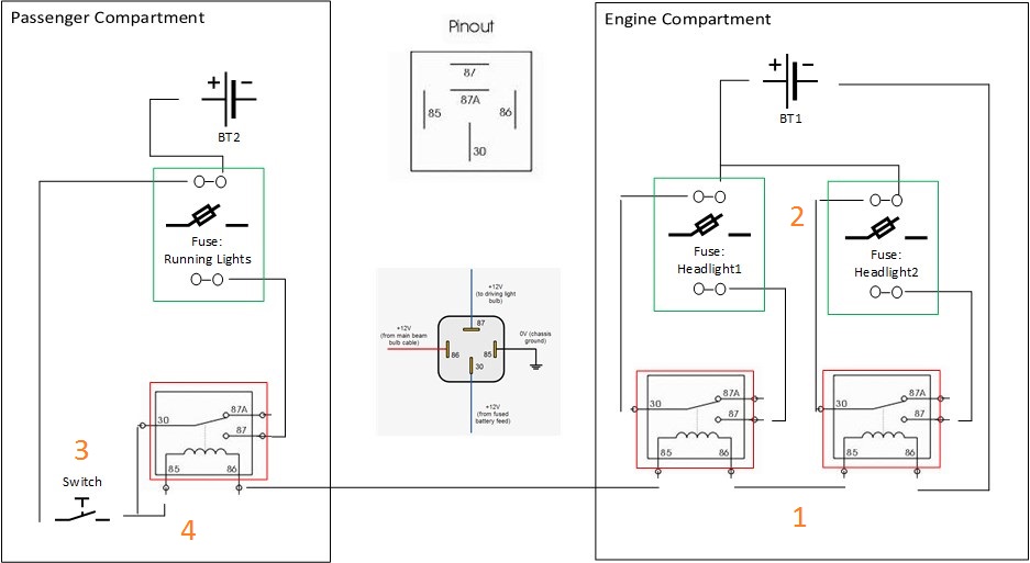
Here is my original diagram, and it seemed tidy at the time. Put the relays in series so that when you flip the switch they’re all energized and share primary power from the fuse tap so that it energizes both the running lights and the relay switch. Use three piggy backed taps and only switch the fuses – no messing with headlight or running light wires. In the diagrams, the green boxes represent a piggy backed tap plugged into the fuse box.
When I got under the hood, I made four design-changing discoveries.
- Relays don’t work in series – Out from one flowing to the In port of another – they have to be wired in parallel.
- Not all fuse boxes are the same. I had room for the piggy backed taps in the passenger fuse box but there was no way they were going to fit in the engine compartment box… laughably so. No room to even think about it.
- Any lit switch is in fact not SPST (Single Pull, Single Throw), they use the power in to light the LED and you can put anything behind that you want (as long as post-LED power will suffice…). They are in fact SPDT (Single Pull, Double Throw).
- Electricity flows like water. You know how your kitchen plumbing goes awry and water from the dish washer (for example) backs up into the sink? The sink effectively has two “outs” and one “in” : dish water coming up the lower pipe is now split between two sinks evenly, yes? Well, split an electric circuit and you can end up with different voltages and current across both circuits, causing a “sag” that may dim your lights, or that the car computer may catch as a malfunction, If you can’t run relays in series, there must be enough resistance to cause an issue with lighting, yes?
How I did it
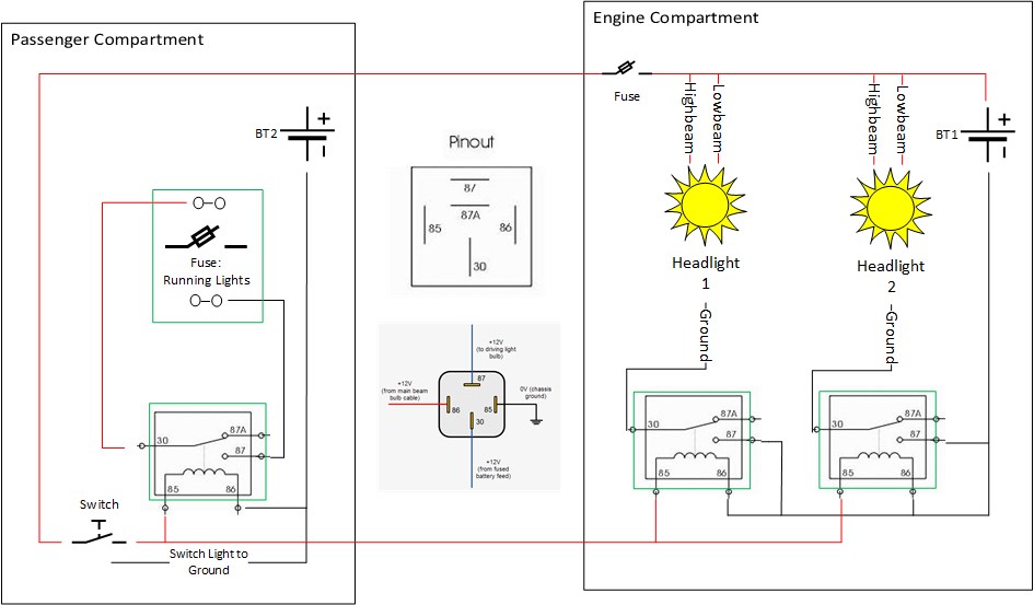
Here is my final diagram. (Note – I depicted the headlights high and low beams as coming straight off positive, I know that’s not right, it’s oversimplified. Also, I didn’t note that the running light fuse came straight off the positive/”hot” as the previous picture – the left side of the piggy backed tap provides power directly.)
- The relays were wired so they each had their own access to “hot” and ground. They still need to be energized via switched power, so the bottom “out” lug on the switch went to a splitter – one to the relay in the passenger compartment, one through the firewall to the other headlight relays.
- I didn’t have room in the fuse box for anything at all, I had to use the relays on the car wiring directly. Since there are high and low beams, it seemed easiest to switch ground through the relay. I used a Chiltons car manual to confirm that the common ground wire was black, dug out and cut into the black wire and wired each new end across the relays, one for each headlight. In practice, I connected ground on the relay to a lug bolt on the car body, not directly to the car battery. Note: ground is common and shared here, it works that way. As per point 4 below, you can’t split or share “hot” the same way.
- All lit switches are Single Pull, Double Throw. When wiring lit switches, connect “hot” to the center pole, put ground (or a low power circuit) up top and your primary load on the bottom. Flip the switch and it directs “hot” to both lugs. Not having a smaller, low power circuit I wanted to energize as well, I just ran the top lug straight to ground so that the light would work when switched on. The bottom connection split to the passenger compartment relay for the running lights, and provided a line through the firewall to the headlight relays.
- I had to run a “hot” wire straight off the battery, through the firewall and into the center pole of the lit rocker switch. As you see in the diagram above, I put a 1 amp fuse right off that lead connected to the battery before the switch so that if there’s a short anywhere, the fuse will blow first thing.
Also:
- I used harnesses for the relays and taped the relay/harness junction so that they would be water resistant. I then angled them all down so that any water present could run out.
- I used heat shrink tubing wherever possible (and wherever could withstand the heat). Electrical tape is sufficient but it’s messy and when things get hot it can slide around. Seal a junction with tubing and shorts pretty much never happen.
- Many cable ties were used to hold wires in place. Notice how when you lift the hood all the wires you see are black, there are no exposed “hot” / positive wires? This is on purpose, so running “hot” wires near the actually-hot engine is a bad idea. I pulled the red wires up and away wherever possible. If you can use plastic, flexible cable conduit, do it.
Update
Hindsight is 20/20 : You can use a 5 pin relay instead of a 4 and wire the lights to be on by default, so that you have to turn on the switch in order to turn OFF the lights. This is preferred as it wouldn’t take power to keep the lights on and make the relays essentially stay energized 24/7/365. Give ’em a break and let them keep the lights on normally so that the exception is turning them off.
To do this, wire your lights to pin 87a on the 5-port relay (my system above only uses 4). Diagram forthcoming.
In Conclusion
Messing with modern cars – with their tiny wires and on-board computers – is a tricky business and one is taking an enormous risk in doing so. If you damage the computer or overrate a fuse and melt something in the wiring harness, it can cost many thousands to repair.
I hope that sharing this project and these details has giving you some ideas that will help you accomplish the same in an “easy”, safe way, such that if there are any mistakes they’ll only result in a blown fuse, nothing more.
It’s possible that, after all is said and done, the light switch in the “on” position will drain the battery since it’s always lit. How long until it exhausts your battery, I don’t know, but it’s more than a couple days. If you’re going to the airport, I recommend parking with the switch in the “off” position.
As always, I welcome all feedback, refinements and other comments below.